Example 3: Sample-and-hold Feedback Control for a Continuous-time Plant
In this example, a continuous-time plant is controlled by a digital controller using sample-and-hold digital-to-analog converter.
Contents
The files for this example are found in the package hybrid.examples.zoh_feedback_control :
- initialize.m
- zoh_feedback.slx
- postprocess.m
The contents of this package are located in Examples\+hybrid\+examples\zoh_feedback_control (clicking this link changes your working directory).
Consider a physical process modeled as a linear system of the form \(\dot x = Ax + Bu\) , defined below. The algorithm (static gain) uses measurements of its output and controls the input of the physical process with the goal of steering its state to zero.
Suppose the sampling device is ideal and that the signals are connected to the plant via a Digital-to-analog converter (DAC) modeled as follows. The digital signals in the cyber components need to be converted to analog signals for their use in the physical world. A DAC performs such a task by converting digital signals into analog equivalents. One of the most common models for a DAC is the zero-order hold model (ZOH). In simple terms, a ZOH converts a digital signal at its input into an analog signal at its output. Its output is updated at discrete time instants, typically periodically, and held constant in between updates, until new information is available at the next sampling time. We will model DACs as ZOH devices with similar dynamics. Let \(\tau_{h}\in\mathbb{R}_{\geq 0}\) be the timer state, \(m_h \in R^{rC}\) be the sample state (note that the value of \(h\) indicates the number of DACs in the interface), and \(v_h \in R^{rC}\) be the inputs of the DAC. Its operation is as follows. When \(\tau_h \leq 0\) , the timer state is reset to \(\tau_r\) and the sample state is updated with \(v_h\) (usually the output of an embedded computer), where \(\tau_r \in [T_{min} , T_{max}]\) is a random variable that models the time in-between communication instants and \(T_{min} \leq T_{max}\) .
A model that captures this mechanism is given by \(\dot\tau_h = -1, \dot m _h = 0\) when \(\tau_h \in [T_{min},T_{max}]\) and \(\tau_h^+ = \tau_h, m _h^+ = v_h\) when \(\tau_h \leq T_{min}.\)
Mathematical Model
Physical Plant
\[\left\{\begin{array}{ll} f_P(x,u):= Ax + Bu, & C_P := \mathbb{R}^{2} \times \mathbb{R}^{2} \\ \\ g_P(x,u):=x, & D_P: = \emptyset, \\ \\ y = h(x) := x, \end{array}\right.\]
where \(x = (x_1,x_2)\in\mathbb{R}^{2}\) , \(u \in\mathbb{R}\) , and
\[\begin{array}{lll} A := \left[\begin{array}{cc} 0 & 1 \\ 0 & -b/m \end{array}\right] \in \mathbb{R}^{2 \times 2}, & B := \left[\begin{array}{c} 1 \\ 1/m \end{array}\right] \in \mathbb{R}^{1 \times 2}. \end{array}\]
Analog-to-digital converter (ADC)
\[\left\{\begin{array}{ll} f(x,u):=\left[\begin{array}{c} 0 \\ 0 \\ 1 \end{array}\right], & C := \{ (x,u) \mid \tau_s \in [0,T_s^*]\} \\ \\ g(x,u):=\left[ \begin{array}{c} u \\ 0 \end{array}\right], & D: = \{ (x,u) \mid \tau_s \geq [0,T_s^*]\}, \\ \\ y = h(x) := x, \end{array}\right.\]
where \(x = (m_s,\tau_s) \in \mathbb{R}^2 \times \mathbb{R}\) , and \(u\in \mathbb{R}\) .
Zero-Order Hold (ZOH)
\[\left\{\begin{array}{ll} f(x,u):=\left[\begin{array}{c} 0 \\ 1 \end{array}\right], & C := \{ (x,u) \mid \tau_s \in [0,T_s^*]\} \\ \\ g(x,u):=\left[ \begin{array}{c} u \\ 0 \end{array}\right], & D: = \{ (x,u) \mid \tau_s \geq [0,T_s^*]\}, \\ \\ y = h(x) := x, \end{array}\right.\]
where \(x = (m_s,\tau_s) \in \mathbb{R} \times \mathbb{R}\) , and \(u\in \mathbb{R}\) .
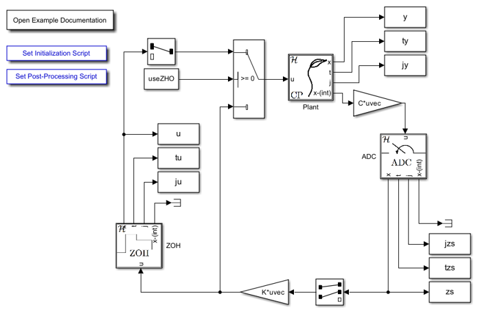
Simulink Model
The Simulink model of the interconnection between the models of the physical process, the sampling device, and the DAC is shown below. In particular, the output of the DAC is connected to the input u of the physical process by a matrix gain K , while the input v of the finite state machine is equal to the output y of the physical process at every sampling instant.
Continuous-Time Plant
The Simulink blocks for the plant subsystem in this example are included below.
flow map f block
function xdot = f(x, u, parameters)
    % Flow map for plant.
    % parameters: [A,B,C,K'];
    A = parameters(:,1:2);
    B = parameters(:,3);
    xdot = A*x + B*u;
end
flow set C block
function v  = C(x, u)
    % Flow set inidicator function for plant.
    v = 1; % report flow
end
The ADC and ZOH blocks are described in Analog-to-Digital Converter and Zero-Order Hold .
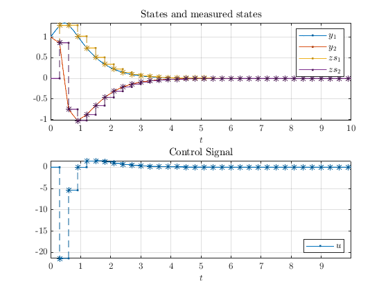
Example output
A solution to the system in this example is plotted below.